17 METER DOUBLE SIDEBAND PROJECT
Built in the Azores by N2CQR CU2JL M0HBR
Send me an e-mail - Comments on this rig are welcome!
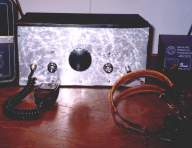
Here's the rig in its budbox cabinet. Front panel is the bottom of a cake pan.
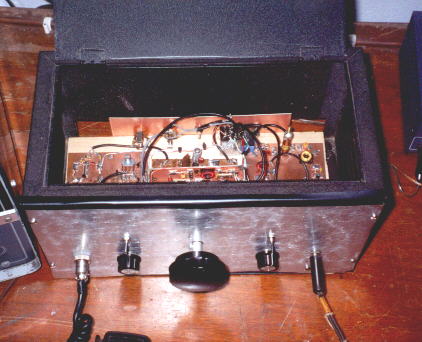
A look at inside. To the left of th main tuning control is the RF gain. AF gain to the right. One swith is the INTERNAL/EXTERNAL RX switch. The other is the SPOT switch for use when using an external RX.
This rig has been working lots of DX: W7, DL, G, VK7, VK1, VP5, KH8... On 27 August I had a 45 minute Q5 QSO with ZL2BCG. Both Jim and I were using dipoles!
Schematic and pictures of VXO circuit
Schematic and Picture of RF AMP board
Pictures and schematic of the receiver board
E-mail reports sent out on the project (to QRP-L and Homebrew@qth.net)
April 24, 2001:
I feel the urge to melt solder. And I want to build a "phone rig." I've always wanted to get on 17 meters (no contests!). I can listen to that band on my Drake 2-B. Here's my plan:
Solid State Double side band suppressed carrier TX based on Doug DeMaw's circuits. Very simple. Sort of a direct conversion transmitter. The oscillator will be on the transmit frequency. I think I'll start out with a VXO (I have the rock). Solid State PA. (Another option I considered would be to put the boards on an old DX-60 chassis and rebuild the 6146 PA stage... but I think that might be overkill.)
I'm going to start out just building a transmitter. I'll build the oscillator first, then the DSB generator. Finally (!) the PA. I'm going to leave room in the cabinet for receive circuitry. It would be very easy (and sort of appropriate) to build a matching direct conversion receiver, but I've had bad luck with them and may decide to build a real superhet RX and make the final rig a Transmitter - Receiver (not a transceiver).
I have an old Bud cabinet that's about the right size. I'm thinking of using the Manhattan technique on the circuit boards.
What do you guys think? Anyone out there built this kind of rig?
73 from the Azores. Bill CU2JL N2CQR
--------------------------------------------
April 28, 2001
I stopped off at a hardware store yesterday and bought some super glue. This morning I used it to build the first stage of the 17 meter DSB rig: the Variable Crystal Oscillator. I used the circuit from Doug DeMaw's "Barebones superhet" (June 82 QST) Very simple. I used a MPF102 instead of the 40673. The stage went together very quickly - Manhattan style is the way to go! I'd been listening to 17 meter SSB as I worked. It was very satisfying when, at the end of the morning, I connected a 12 volt battery to the circuit board and heard my new oscillator through the receiver. I got very good "swing" in the crystal -- -lloks like > 20 Khz.
I think I'll build a direct conversion RX to go with this rig -- this way I'll be listening to both sidebands at the same time and will be better able to avoid interfering with nearby stations.
73 from the Azores Bill CU2JL N2CQR
-------------------------------------
May 5, 2001
There has been steady progress on my 17 meter DSB rig.
With the VXO completed (or so I thought!) I moved on to the microphone amp and the balanced modulator. The mic amp was a 741 op amp -- construction and testing were uneventful. I used Manhattan style construction -- the chip was crazy glued to the board, leads up.
The balanced modulator went together very well. Given that I'm 900 miles from the nearest electronics store, I was very pleased to find that I had all the needed components in my junk box. I used hot carrier diodes (that a FB member of the NOVA QRP club had been giving away a club luncheon). I picked two that had forward resistances that were very close. I didn't have the 250 ohm balancing pot that Doug DeMaw's circuit called for, so I used a small 2K pot with an appropriate fixed value resistor across it. I tried to keep the physical layout of the balanced modulator symmetrical.
A problem cropped up when I tried to test it. When I connected the VXO to the LO in port of the modulator, the VXO shut down. I played around with some of the feedback circuit values, but no joy. So I just used some of the extra space on the VXO board to build a simple JFET amplifier circuit (really just for isolation). This solved the problem.
I could now test the balanced modulator. Putting an RF probe (to a DMM) at the modulator's output, I turned on the VXO and tried to see if I could balance out the carrier. Worked like a charm! Just about in the center of the pot's movement, output dropped to near zero. Then, to see if an incoming audio signal would UN-balance it, I injected some noise into the mike in port. Output jumped considerably.
Next I built the first RF amp stage, just a simple class A amp using a 3904 transistor. I goofed by getting the collector and emitter confused (it didn't amplify too well that way!) but once I got it straightened out, I was getting the desired gain.
Then came the cool part of the morning: I connected a microphone to the modulator and a six foot piece of wire at the output of the RF AMP. I tuned my Drake 2-B to the output freq. Then I balanced out the carrier. Then I spoke into the mic. DSB through the Drake 2-B. I could hear some RF getting into the input, but other than that it sounded pretty good! Some shielding will take care of the RF problem.
NEXT STEP: PA. I'm looking for a circuit that doesn't require any exotic parts (defined as parts not currently in my junk box -- some of those toroidal cores used by W1FB are just not on hand). Any suggestions? Also, I'm short on 1 mH RF chokes. Any thought on how I can wind my own?
-----------------------------------------------
May 8, 2001
(Sorry for sending this twice: I goofed up the address on the first attempt.)
I noticed that the voltage level at the LO port on my balanced modulator was very low. Doug Deaw wrote that it should be 1 volt rms, but I'm measuring only .1 volt.
I think the problem is that my VXO has a high Z output while the LO port is low Z. The VXO has a JFET amp and was deigned to connect to the gate of a MOSFET. The LO port is one coil on a 12 turn trifilar balanced modulator tranformer.
With no load on the VXO output I get about 1.89 volts rms. The problem, of course, arises when I connect the output to the balanced modulator LO port - then I only get around .1 volt at the port.
I've been playing around with an impedance matching transformer using a toroid core. with 12 turns on the primary and 3 on the secondary I can get the input voltage up to about .5 volts.
Am I heading in the right direction? Any other suggestions on how to handle this? Could it be that I just need another stage of amplification in the VXO, or should I continue to experiment with the transformer?
-------------------------------------------------
May 23, 2001
My 17 Meter DSB QRP rig has passed its smoke test. I built a two stage linear amplifier for it and it looks like I'm getting about 1.3 watts out. The transmitter is currently on 4 separate PC boards spread out on my operating table. Clip leads connect it to my 12 Volt Gel Cell. I'm using a Drake 2-B as the receiver.
17 meters has been in good shape. This morning I listened to a nice QSO between a VK7 and a W6. But so far I haven't made a QSO with the new rig.
I was hoping that someone out there could point their beam at the Azores and listen for my QRP DSB signal. My VXO tunes from about 18.110 to about 18.130. I can be on the air tomorrow (24 May) from 0530 UTC to 0730 UTC. Please let me know if you can listen for me during this period.
--------------------------------------------
May 27, 2001
I made my first QSO with the 17 meter DSB rig, but it was more of a test than a QSO: after much fruitless calling I was forced to resort to a sked. CU2BD pointed his beam at me from the other side of Ponta Delgada (3km)... and still had trouble hearing me. He said the audio sounded OK, but very weak.
The problem is low output in the DSB mode. I think I've localized the trouble to the Balanced Modulator. This is a simple transformer/two diode circuit. It appears on Page 139 of W1FB's QRP Notebook.
I am able to 'balance out' the RF. When I unbalance the modulator(using the balance pot), I get about 1 watt out of the final (this is about right). But when I once again balance out the carrier and try to modulate, I can barely make the SWR/Output meter wiggle. Even when whistling, I can barely get the meter to move. I am modulating the signal, but just not enough.
I don't think the problem is insufficient audio. My audio amplifier (a 741 op amp) is working fine. And I tried injecting a 1 khz tone (at about 1 volt rms) into the AF port of the balance modulator -- no joy. I put the same signal into the input of the Op amp. Again, no luck.
So it is as if half of the balanced modulator (the RF half) is working fine (I can null out the carrier) but the audio portion seems unable to "unbalance" the modulator properly. I think the audio should be able to produce a level of "unbalancing" similar to what happens when I turn the balance pot to either end, but so far it is not even close.
I'm using two Motorola IN5821977 Hot carrier diodes. The both show forward resistance of about 5 ohms. (This is what I had in the junk box -- do you guys think this is a suitable component?)
I'm stumped. Anyone have any ideas on what's wrong or how I should proceed?
-----------------------------------
May 28, 2001
With lots of help and advice from list members, I got the modulator working on my homebrew 17 meter DSB rig. I checked and re-checked everything and finally decided to pull out the Schottky diodes I had in there and try some ordinary diodes. (I don't even know the designation for the new ones -- I picked them up at a Radio Shack a long time ago and they have been lurking in my junk box ever since.)
BINGO! With the new diodes I was able to null out the carrier and get approximately 1 Watt PEP our of the rig. I'm sure the audio doesn't sound great, but I can work on that later. For now, I'm very happy to see the power output/SWR meter bouncing nicely as I call (futile!) CQ's!
I don't know why the other diode's didn't work. They tested fine, with high reverse and low forward resistance.
Thanks again to all those who helped. I will continue to keep you posted on progress (and I will probably be asking for more help on future problems).
I think I'll be building another RF amp stage to get me up to 5-10 watts or so. Then it will be on to the companion Direct Conversion Receiver. This is, after all, a Direct Conversion transmitter!
------------------------------------------------------
June 3, 2001
After fixing my balanced modulator problem, this week I was trying to get the audio coming out of my 17 meter DSB rig to sound, well, human. There was clearly something wrong, something very nonlinear, in the RF amp that I'd cobbled together.
Yesterday morning, as I considered my options, I remembered that the 30 meter CW QRP rig that I'd built while in the Dominican Republic had a very nice, robust broadband driver and RF amp (to MRF472s in parallel). I haven't been using the 30 meter rig very much (I really hate using the DC receiver that I built with it), so it didn't take long for me to convince myself to pull out the transmitter board and convert it into the PA for my 17 meter DSB rig.
It looked like all stages in the 30 meter rig (VXO controlled 6 watter from QRP Classics) were class A -- except, of course, the class C final. I quickly built a little diode-based circuit to lift the bases of the MRF472 to a voltage that would keep things in Class A. I disconnected the 30 meter output filter (I'll rebuild it for 17 later) and hooked the 17 meter dipole to the .1 cap that goes to the final.
The driver transistor was running a bit hot so I improvised a heat sink out of a few inches of copper tubing and some heat sink compound.
I used the microphone from an old Yaesu memorizer transceiver. I had a bit of trouble getting the mic to stay connected so I whipped out some duct tape and stuck the connector and cables right to the desk.
T-R switching is accomplished via the T-R relay that usually connects my Drake 2-B to my HT-37. So to transmit I must connect the DSB transmitter's ground lead to the Gel Cell and then put the HT-37 in transmit mode. This will all get easier, of course, when this rig is mounted in a cabinet.
This morning I had another schedule with Felipe, CU2BD to test the rig. I made the final connections with just minutes to spare. While I was waiting for Felipe to arrive on freq, I heard CT2FYI calling from Lisbon. I gave him a shout, got a good signal report (Lisbon is about 900 miles west of me!). Then Felipe came on and told me the audio sounded good. A few minutes later I worked D44BS in the Cape Verde Islands (I got a 55). Then came GB2RN on the HMS Belfast in London - he also gave me 55.
It was a lot of fun getting this thing to work. It looks like I'm getting about 2 watts PEP out. And I don't see any signs of distortion. I'm going to see who else I can work.
Next step will be to put the rig in a cabinet and build a more comfortable T-R arrangement. Then I'll be looking for suggestions on Direct Conversion RX circuits.
Thanks again to all those who've been helping out with advice and encouragement.
-----------------------------------------
June 4, 2001
In my last update I said that Lisbon was 900 miles west of me. I suppose that would put the Azores in the Med! I attribute the error to the early hour, solder fumes and the excitement of getting the DSB rig on the air.
The transmitter continues to yield great contacts. Yesterday afternoon I called CQ on 17 and got a response from Jorge, EA5GQI/M, on the road in Alicante, Spain. Jorge was appropriately surprised when I told him I was running 1 watt from an HB transmitter. He pulled to the roadside, recorded my transmission and -- from his car -- sent my signal back to me. So I got to hear my own audio. Very cool!
Last night I again dared to call CQ and got a response from OZ4B in Copenhagen. Bo gave me a 55 and said the audio sounded good. Not bad for an audio section that consists of a 741 op amp! Bo also suggested that I put the rig on 12 meters. Hmmm...
These contacts were great fun, but the big DX thrill came this morning. U.S. stations were coming in and I was hoping to work the homeland. No luck. But just as I was about to give up, I heard Gerry, VK7GK, on Tasmania say that's he'd listen for one more. I gave him a shout. The DSB rig was 44 down-under down-under. We had a nice QSO.
When I was a teenage ham, the first time I'd worked a station in that part of the world, I woke up my parents to tell them of my feat! Good thing my wife was already awake, because I once again went bounding up the stairs with the big news. I'd been hoping to cross one ocean, and ended up crossing two.
On the tech side, I'm thinking that my decision to recycle the broadband RF amps from the 30 meter rig will yield a big, unexpected benefit: It will now be very easy to put this rig on other bands. All I'll have to do is get the appropriate crystal for the VXO and build a group of band-specific output filters for the final amp.
You guys have got to build some more phone rigs! This is really fun. You can hear the surprise in the voice of the guy at the other end when you tell them about the power level and the brand name (HB) of the rig. Phone QRP is a LOT easier than I expected, and I'm 10 db below the upper limit on output power for QRP status. People are answering my CQs!
When the dust settles, I'll draw up the schematic and post it (with pictures) on my web site.
-----------------------------------
June 18, 2001
While I have been having a lot of fun having QSO's with the three boards spread out on the operating table, the Transmit/Receive switching arrangement was getting kind of tiresome. I've been using my Drake 2-B as the inhaler, and for T/R switching I've been using the external relay that is controlled by the T/R switch on my Hallicrafters HT-37. On receive I'd also have to shut down the transmitter by removing the ground connection to the Gel-Cell. Like I said, kind of tiresome. And frequency spotting required even more gymnastics! To make matters even worse, it was taking a few seconds for the electrolytics in the microphone amp circuit to get going, so there would be an annoying delay every time I went from R to T... you know, just long enough to have the other operator start calling CQ again. And the HT-37 was heating up the room! Clearly something had to be done.
I found a suitable 4 pole double throw 12 V relay in the junk box and this morning I rigged up a much better TR scheme. The relay is superglued to the piece of pine that serves as the chassis. For the time being one pole switches 12 volts DC to all the transmitter circuits except the mic amp, which is powered up all the time. Another pole mutes the receiver and a third switches the antenna. I realize that the relay is a waste of energy, and that there are probably better ways of doing this, but this was a very simply way to allow for Push to Talk operation. PTT was a major improvement!
Getting the boards screwed down to the chassis was another big step toward making this thing seem like a real radio. I have the DSB generator on the left and the small RF AMP board in the back center. The VXO box is elevated a couple of inches above the chassis by some pieces of wood -- this will allow the main tuning cap to be at a comfortable position on the front panel. The board on the right side has been left open for the DC receiver. I'll post some pictures next week.
Following Doug DeMaw's advice about raiding the kitchen for radio cabinet material, I got ahold of a couple of suitably-sized aluminum cooking pans. I should be able to make a good front panel from them.
So now my thoughts turn to the receiver. Obviously direct conversion using the RF from the VXO.
I'm thinking about using a diode ring mixer for the RX (I hate AM breakthrough). I have to leave the VXO on all the time, and I'd like to avoid switching the VXO output from the RX to the TX (potential for freq shift under different loads) but I'm a bit concerned that adding another Low Z port to the VXO output might cause the input voltage at the TX LO input port to drop considerably. Any ideas on this? How about an FET isolation amp between the VXO and the diode ring detector? Or how about using one of those TV signal splitters at the output of the VXO?
I want to use discrete components in the RX. I think I want an RF amp stage (maybe grounded gate) just to get some additional tuned circuits between the mixer and the antenna. After the mixer I'll want some simple audio filtering (to get at least some selectivity). And enough audio to drive a small speaker. Any circuit suggestions?
----------------------------
June 28, 2001
I put some recent pictures of the 17 meter DSB rig on my web site. Just go to the URL that appears below and click on the "17 meter DSB" link.
I decided to use one pole of the 4 pole double throw TR relay to switch the VXO output from the transmitter balanced modulator to the receiver's mixer.
Looks like the RX will be direct conversion with one stage of RF amp, diode ring mixer, simple SSB low pass filter, and enough audio amplification to drive a speaker. (I'll probably resort to an LM386.)
-------------------
July 11, 2001
I've been having so much fun with the 17 meter DSB transmitter that I've been delayed in building the receiver. Let me give you an example of the 17 meter fun: On 5 July at around 0600 UTC I called CQ on 17 meters. With a regulated 13.8 volt supply the rig is putting out around 5 watts PEP (that's DSB, so there is a lot of energy in the other sideband and some in the not fully suppressed carrier). VK1MJ came back. Mike gave me a 52, but I was very pleased. This was the second time in a month that he'd answered my CQ. When I finished with Mike, I called CQ again on the same freq and was answered by KH8/N5OLS in American Samoa. I was 55. Don and I had a nice ragchew about island life (Atlantic and Pacific). My theory is that the radio gods smile on homebrewers.
So you can see why I've been neglecting the soldering iron. Fortunately conditions deteriorated a bit during the last week or so -- this allowed me to build a couple of stages on the DC receiver that will accompany the TX. First I built the four diode mixer. I used the same kind of small signal diodes that worked well in the TX's balanced modulator. Doug DeMaw's circuit called for the use of FT-37-43 cores for the transformers, but I'd found that core to be a bit small for my fingers, so I used FT-50-43 cores (same material, just larger diameter). I quickly connected the TX VXO and tests indicated that the thing was in fact mixing.
Next I built a grounded gate JFET (MPF-102) RF amp with tuned circuits at the input and output. Toroids and trimmer caps. Manhattan building techniques seemed to help a lot in keeping this Amp from oscillating. Soon I had the amp connected to the mixer. From the junkbox I found an LM386 AF amp circuit that I'd built for an earlier project. That went to the mixer output. Now I had a receiver.
I think it is really cool when you first coax a signal out of a new RX. Last night I was peaking the trimmer caps on the RF amp when all of a sudden I heard some very faint SSB chatter. I tuned the VXO, tweaked the caps a bit more and there it was, the unmistakable accent of a G station. I went to be a happy HBer.
Now I have to build a real AF amp for this RX. I'm tired of the standard LM386 or 741 op amp circuits. Isn't there something out there that is 1) simple 2) uses discrete components and 3) can drive a speaker? Any suggestions?
----------------------------------
July 16, 2001
I added a 100 db audio amplifier after the mixer in the Direct Conversion receiver. It's the three transistor direct coupled amp that appears on page 76 of SSD. I used 2N2222s. A board mounted 10K pot went between the mixer and the input of the amp. I built it Manhattan style with some ugly thrown in. With high impedance headphones the amp works very nicely. You get that great sensation of hearing the band "directly."
The high impedance headphones I'm using are very old. They were manufactured by "American Bell" in Wayland N.Y. I felt like a real radio pioneer when I put those things on.
I take back all the bad things I said about DC receivers. This one works very nicely. The VXO keeps it stable and the 4 diode mixer seems to have eliminated the AM detection problem (admittedly this problem is easier to beat at 18 Mhz than at 7 or 10).
Just to review, here's the RX lineup: Grounded gate RF amp (MPF102) with tuned circuits in the input and output. 4 diode mixer (ordinary switching diodes) with two toroidal transformers. LO is the VXO from the TX: JFET oscillator, source follower, RF amp. AF amp described above.
Question: In the mixer circuuit that I used, at the mixer's AF output port, Doug DeMaw had a 10k ohm resistor to ground and a 1 K resistor between the transfomer and the output cap. In another similar circuit, the output went across an RF choke to ground. Are these simple circuits in lieu of a diplexer? Do I need a diplexer?
I'm going to try to add one or two more AF stages to see if I can drive a speaker (without having this thing take off).
There is some annoying AC hum when I run this RX off an AC power supply -- if filtering and shielding doesn't fix this, I may have to limit myself to battery ops.
Last night I was tuning through 17 with the new RX and heard a loud CQ from ON4AAM. I hit the PTT and gave him a shout. I was 56 - 57. I was very pleased with the first transceiver QSO with this rig.
-------------------------------------------------
July 26, 2001
I'm having a lot of fun with the DC receiver that I built as part of my evolving 17 meter DSB transceiver. (I've posted pictures and a schematic at http://www.gadgeteer.us Just click on the 17 meter DSB link.)
Right after I built the receiver, I was browsing through some old QSTs and came across the November 1968 issue. Wes Hayward, W7ZOI, and Dick Bingham, W7WKR, had an article entitled "Direct Conversion - A Neglected Technque." This must have been the piece that launched the DC revolution. Neglected no more! I knew I'd been on the right track when I discovered that the RX described in the article was very similar to the one I'd just built. Same product detector and AF AMP. (This came as no surprise as I'd taken the circuitry out of SSD.)
My previous experiences with DC RXs were pretty bad -- lot's of AM breakthrough, common mode hum, etc. I think I avoided many of these problems with this RX by staying away from the standard NE602-LM386 neophyte designs. And I've been helped by the fact that earlier rigs were built for 10 an 7 Mhz, where SW broadcast interference is much more intense than at 18 Mhz. The AC hum problem was cured with one toroid between the PS and the rig.
I have had some problems with AM breakthrough. On Sunday morning at 0800 UTC, Radio Exterior de Espana fired up, apparently with its antennas aimed in my direction. I consulted their schedule and I think I was hearing either their 17.77 or 17.88 Mhz broadcast. Too close for comfort. Pretty much wiped out the ham signals I was listening to. I went back and very carefully re tuned the two tuned circuits in the RF amp (front end). I found that I could peak the both of them in such a way as to eliminate most of the AM breakthrough problem. I know many people advise against RF amps ahead of the mixers in DC receivers, but I wanted to get the two tuned circuits in there. I'm glad I did.
The RF amp can, however, give me too much gain and make things very noisy. I've seen people use 10K pot as an attenuator at the antenna port, but I came up with what I think is a more elegant solution: I put a 2k pot on the 12V line going to the MPF-102 in the front end. So I can control the voltage going to the the drain of the grounded gate amp. This serves as a very smooth RF gain control. I use it a lot.
The receiver is stable and sensitive. Of course it is very broad and I hear "both sides." But I'm very satisfied. There is, of course, still room for improvement.
I'm still using the headphones. The rx is working so nicely that I'm reluctant to add the extra stages needed for speaker ops. But I suppose I'll eventually give it a try. I don't even have an audio gain control. (The RX in the Nov. '68 article didn't have one either. The authors suggested detuning the caps in the front end if you needed to reduce gain.)
One deficiency I can hear involves very strong SSB signals. Even if they are completely out of my tuning range, I can hear the "monkey chatter." Tuning the RX does not affect the sound. Same chatter no matter where I tune. Anyone have any thoughts on how to cure this? I don't know if the stations involved are splattering or not. I'm thinking that a low pass filter between the detector and the audio amp might help. I'd be looking at a simple, passive filter -- I don't want to put in any complex active filter circuits. Thoughts?
I used some ordinary switching diodes in the mixer. Does anyone think that the RX would work significantly better if I replaced them with the recommended Schottky diodes?
I'd been thinking that I'd need a lot of shielding around the RX board to make this thing work properly, but so far it is working fine with no shielding. The VXO is in a box, so I suppose that helps with some of the problems often seen in DC RXs. Anyone think I should put in some more shielding?
---------------------------------------
August 5, 2001
I've been trying to add more AF gain to my direct conversion EX for 17. I have a 100db, three transistor (2n2222a) direct coupled amp similar to the one from SSD. (See my web page for the schematic -- URL in the sig below.) This amp works very well -- it is very quiet and does not take off on me. I have a grounded gate RF amp (about 10 db) ahead of the mixer. I think there is about 8 db of loss in the mixer.
I know the RX would work better with more AF gain. When I plug a little amplified computer speaker in the AF out from the 100 deb amp, I can turn the RF gain very low and the whole system seems to work better.
I tried adding an MPF102 amp stage ahead of the 100 db amp. It added far too much noise. Then I tried an additional 2n2222a stage AFTER the 100 db amp. Again, way too noisy. Today I built a 40 db amp out of the ARRL data book. Again, too much noise.
What am I doing wrong here? Am I proving that there is wisdom in the decision to go with LM386s and other ICs as AF amps? Is it really this difficult to get sufficient AF gain in a DC RX using discrete transistors and simple circuits? Why is it that the 100 db amp is so quiet and works so well, while the others add so much noise?
BTW: I had some AM detection problems with a RADIO EXTERIOR de ESPANA SW broadcast on 17.7 Mhz. I put a series tuned circuit between the RF and ground. A bit of tweaking knocked the SW signal down nicely while leaving 17 meters intact.
Don't get me wrong -- the RX is working nicely already. When I talk to Amadeus, CT2HGL, I can hear his parakeets in the background. And I can hear the seagulls outside G3IUE's window! Recent DX: 4Z4, 9K2, Shettland Islands....
----------------------------------------------
August 27, 2001
Poor band conditions on 17 allowed me to put down the microphone and work on the rig.
Recognzing the inherent shortcomings in the receiver that consists of only 4 transistors and 4 diodes (other than the VX0), I decided to build a switching arrangement that would permit me to go to an external receiver (my trusty Drake 2-B) with the flip of a front panel switch. I used a 3PDT switch and a small relay, and a second switch (to turn on the VXO for spotting). The circuitry works very well -- when the DC receiver can no longer handle the QRM, or when the weaker signals get lost in all the noise that is getting through the relatively wide passband of the DC RX, I just throw the INT/EXT RX switch, turn on the VXO, quickly zero beat the 2-B and I'm in business. (Of course, the Drake 2-B died just as I completed the INT/EXT circuit! Thank God I had a spare rectifier tube in the junk box.)
Here's a question for the groups: Am I right in thinking that when the going gets rough (QRN, QRM) the simple DC receiver will simply not be able to compete with a good superhet like the 2-B? I think the passband (and the noise) will always be about double that of the superhet, correct?
As for my AF amp problems, after many failed attempts to add additional AF amplification, I came across an article in QQ that discussed the big differences in sensitivity among HI-Z headphones. This prompted me to reach into the junk box and experiment. I found a set of old military headphnes that were significantly more sensitive than those that I'd been using. So I no longer have a need for more amlification. (I'd given up on the idea of having a speaker in the cabinet. If I want to listen on a speaker I can just switch to the 2-B.) With the high sensitivity phones, I needed to turn down the AF gain -- so I put a 10k pot between the output of the 100 db pot and the headphones. (I didn't want to invite feedback by putting the long leads at the input to the AMP.)
My problem with the overload of the AF amps by mixer products beyond the audible range seems to have been reduced significantly by turning back the RF gain to minimal levels. Jake, N4UY, is sending me some 88mh toroids. I'll try these in the diplexer circuit to see if some additional low pass AF filterng will help.
Here's a TX question: Why did Doug Demaw use a balanced modulator with only 2 diodes? Wouldn't he have gotten better carrier surpression with a 4 diode arrangment? Could it been that it wouldn't have had much effect on the signal? (My carrier surpression doesn't seem to be that great -- I can see about 250 mw of carrier when I push the PTT down. Output PEP is probably 5-8 watts.)
I put the rig in an old Bud cabinet and used the bottom of a
cake
pan
as the front panel. I think it looks pretty good. Pictures on my web
site.